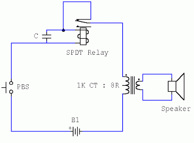
Buzzer In Circuit Diagram
Buzzer switch bulb circuit led schematic connect leds using operated battery electrical resistors same voltage Simple buzzer circuit Buzzer circuit diagram novel simple circuits alarm audio electronic beeper alarms relay speaker next security gr schematics gif projects transformer
circuit design - How to connect a bulb and buzzer to be operated by one
Simple magnetic buzzer circuit with um66 ic – circuits diy Simple novel buzzer circuit diagram What is the working principle of the buzzer?
Circuit design
How to vary the volume of a buzzerBuzzer circuit volume beeper electric vary circuits sound representation real life gr next Buzzer circuit magnetic simple ic diy4 ideas of simple door buzzer circuit diagram.
Buzzer circuit simple circuits beeper gr next buildBuzzer piezo circuit simple diagram make electronic circuits beeper wiring electric using audio volt projects homemade explained hobby automotif feedback Buzzer circuit door diagram simple ic timer bell using sound eleccircuitBeeper buzzer circuit page 2 : audio circuits :: next.gr.

Buzzer working principle passive active distinguish
.
.


4 ideas of simple door buzzer circuit diagram | ElecCircuit.com

Simple Buzzer Circuit - Piezo Electric Buzzer Explained | Electronic

Simple Novel Buzzer Circuit Diagram | Electronic Circuits Diagram

Simple magnetic buzzer circuit with UM66 IC – Circuits DIY

How to Vary the Volume of a Buzzer

circuit design - How to connect a bulb and buzzer to be operated by one